字體:小 中 大
 |
|
|
|
| 2010/10/07 09:23:49瀏覽787|回應0|推薦0 | |
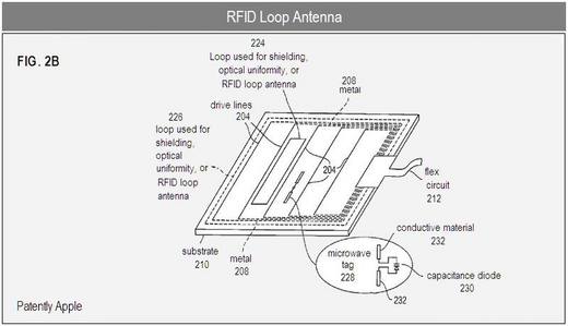
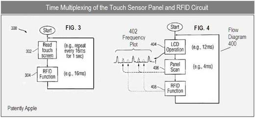
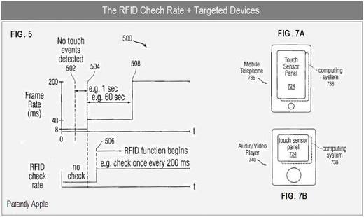
Patent Summary Apple's patent relates to the efficient incorporation of RFID circuitry, either reader or remote unit circuitry or both, and in particular the RFID antenna, within touch sensor panel circuitry. In particular, the RFID antenna could be placed in the touch sensor panel, such that the touch sensor panel could now additionally function as an RFID transponder. In this manner, no separate space-consuming RFID antenna is necessary. In one embodiment, loops (single or multiple) forming the loop antenna of the RFID circuit (for either reader or tag applications) could be formed from metal on the same layer as metal traces formed in the borders of a substrate. The metal traces are used for routing sense or drive lines of the touch sensor panel to one edge of the substrate so that they could be connected to a flex circuit. Forming loops from metal on the same layer as the metal traces could be advantageous in that the loops could be formed during the same processing step as the metal traces, without requiring a separate metal layer. Conductive material other than metal could be used as well. In other embodiments, conductors formed in the shape of loops and normally provided for other functions could be multiplexed to serve as the loop antenna when the handheld device is in an RFID mode. For example, a loop around the perimeter of a touch sensor panel layer, used primarily for optical uniformity or shielding, could be held at a particular potential or ground during normal use, and multiplexed to transmit or receive AC coupled signals when the RFID circuit is to be used. In some embodiments, the embedded RFID circuit could be powered by the same power supply that powers the hand-held device incorporating the touch sensor panel. If powered, the embedded RFID circuit could be used as a reader or a tag. In other embodiments, the embedded RFID circuit could be unpowered, and used exclusively as an RFID tag. The RFID System Apple's patent FIG 1 shown below illustrates an exemplary conventional RFID system, which could include an RFID reader and an RFID tag. Used as an RFID Reader In one embodiment, as noted below in patent FIG. 2a, a handheld device containing embedded RFID circuit 214 could act as a reader configured to read RFID tags affixed to items in a store. After reading the RFID tag to identify an item, the handheld device could then access the Internet or the store's intranet to get price and other information such as product specifications and the like. In this manner, price and other information could be updated by the store as needed. Alternatively, the RFID tag could simply provide fixed price and other information to the reader. Used as an RFID Tag In another embodiment, the handheld device could act as an RFID tag configured to provide information to an RFID reader. This embodiment could include a badge reader function, where a user could simply swipe the handheld device close to an RFID reader to gain access to a building, room, file cabinet, desk drawer, computer, workstation, copy machine, facsimile machine, and the like. In another embodiment, the handheld device can be a remote unit configured to be used as a credit, debit or gift card, so that the device can be used to pay for items, services, train or subway fares, etc. at gates, vending machines, and the like. Used as Both a Reader and Tag In yet another embodiment, the handheld device could be used at different times as both an RFID reader and an RFID tag. For example, two devices could be used in close proximity to exchange information such as contact information. One handheld device could be set to a receive mode, where embedded RFID circuit 214 could be configured as an RFID reader to initially drive the RFID reader's loop antenna to generate magnetic flux. The other handheld device could be set to a transmit mode, where embedded RFID circuit 214 could be configured as an RFID tag to initially receive magnetic flux, and when sufficiently energized, transmit information such as contact information back to the RFID reader. The configuration could be performed by the users of the handheld devices, and upon configuration of the devices, the devices could additionally exchange handshaking or other control signals prior to transmitting and receiving the desired information. Apple's patent FIG. 2b illustrates several exemplary loops formed on the same side of a substrate as the drive lines that can serve as RFID loops. Apple's patent FIG. 3 shown below is a flow diagram illustrating an exemplary time multiplexing of the touch sensor panel and RFID circuit. Apple's patent FIG. 4 shown above is a flow diagram and frequency plot illustrating an exemplary time division multiplexing and frequency division multiplexing of the touch sensor panel, LCD, and RFID circuit. Apple's patent FIG. 5 shown above is a plot of frame rate versus time, illustrating an exemplary change in the frame rate of a panel scan over time and how the RFID function can become operational at the proper time. Apple's patent Figures 7a and 7b simply illustrate that Apple's proposed RFID reader is aimed to debut on devices like the iPhone and iPod touch. Apple credits Michael Rosenblatt and Steven Hotelling as the inventors of the patent application entitled "Touch Screen RFID Tag Reader." The European patent EP 2232627 which was published on September 29, 2010, shows us that the priority US patent was originally filed in 2007. For those wishing to review the deeper technical points of the patent could review the European patent equivalent under WO 2009085777 which was published in 2009. Apple's patent notes that it incorporates the content of a book entitled "RFID Handbook: Fundamentals and Applications in Contactless Smart Cards and Identification" by Klaus Finkenzoeller, John Wiley & Sons, Ltd., 2003." Notice: Patently Apple presents only a brief summary of patents with associated graphic(s) for journalistic news purposes as each such patent application is revealed by the U.S. Patent & Trade Office. Readers are cautioned that the full text of any patent application should be read in its entirety for further details. About Comments: Patently Apple reserves the right to post, dismiss or edit comments. For more background, see our Apple patent archives on NFC - RFID technology. 資料來源: patentlyapple 2010/10/4 (http://www.patentlyapple.com/patently-apple/2010/10/apple-patent-iphone-display-may-double-as-an-rfid-transponder.html)
|
|
| ( 興趣嗜好|電腦3C ) |