字體:小 中 大
 |
|
|
|
| 2021/10/07 12:23:06瀏覽549|回應0|推薦0 | |
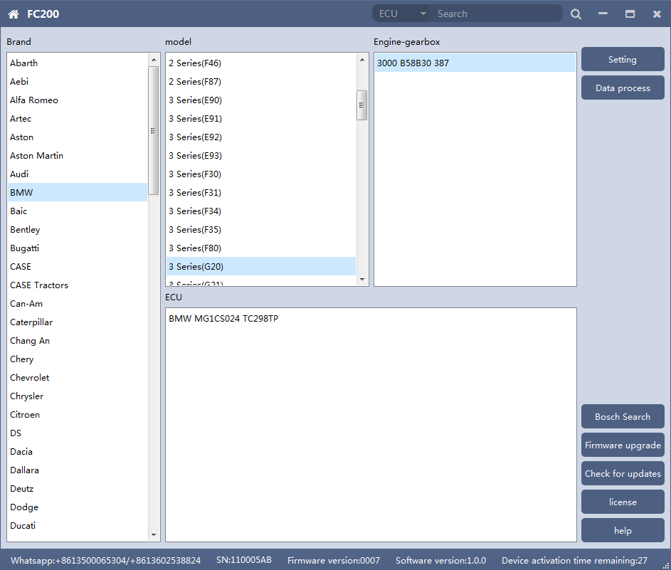
CG FC-200 is arriving after 3-5 working days delivery on schedule, it will be used for ECU /EGS ECU clone, it is claimed to cover 4200 kinds of ECU and 80% of the models on the market. And it is claimed to be capable of data processing, module cloning, disassembly matching, DTC shielding, Immobilizer closed, ISN acquisition, Vin modification etc. If it is as good as promised? Read the following parts. 1. Software Use
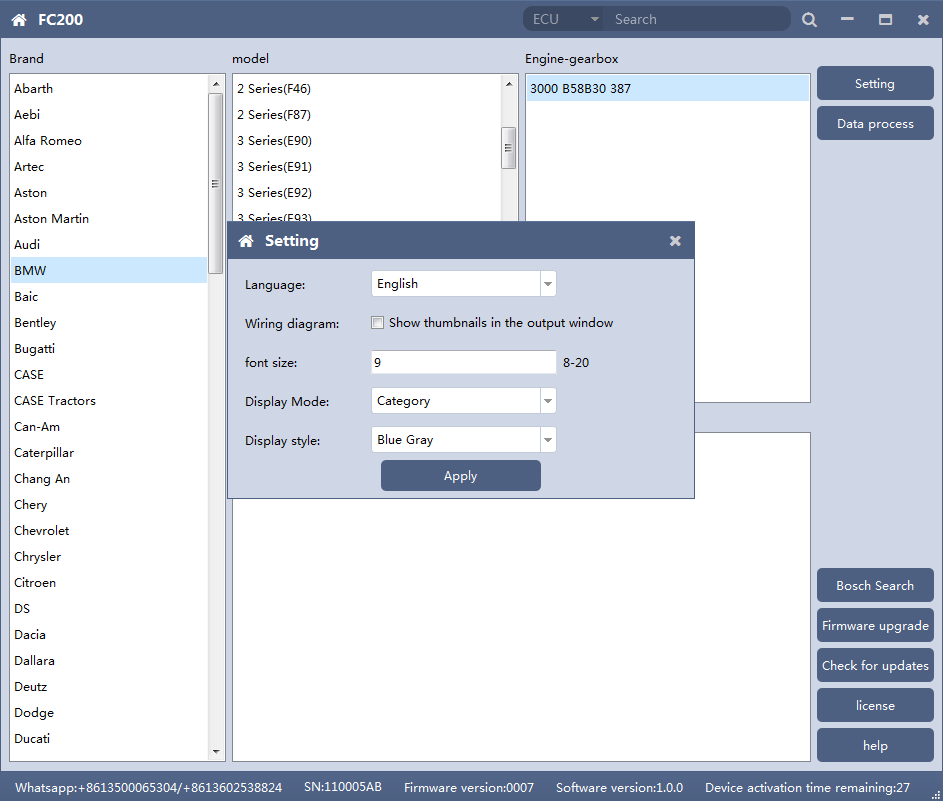
The functions on right side are are: 1. Setting
1.1 Display Method
◎Select category display
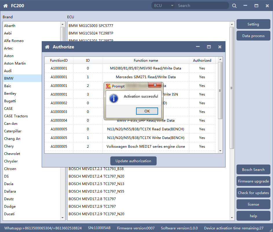
2. Device Authorization
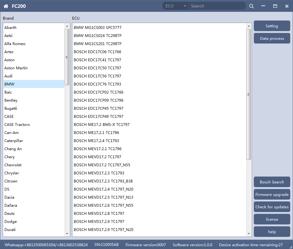
◎If “No” is still displayed after updating authorization, please contact the manufacturer 3. Device search function (frequently-used)
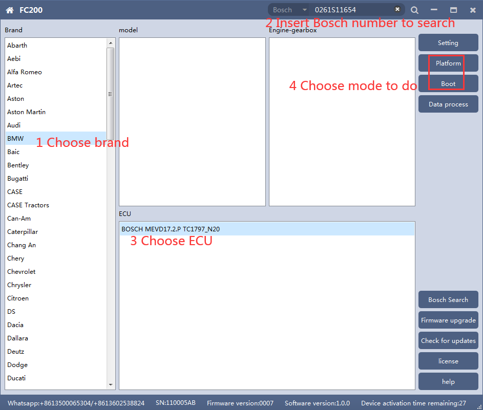
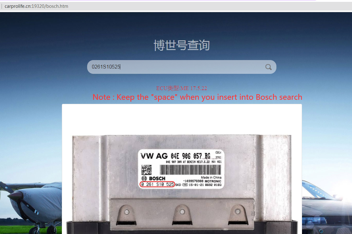
◎Bosch number search
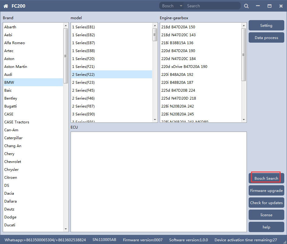
◎Bosch number query (click “Bosch search”)
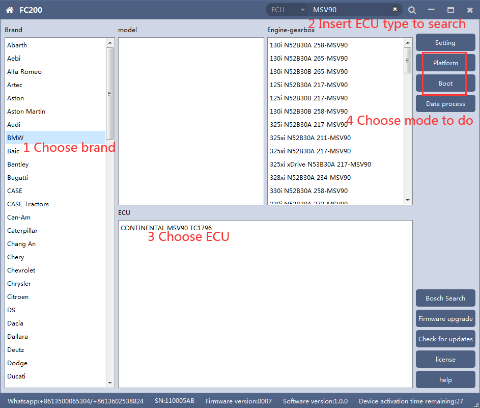
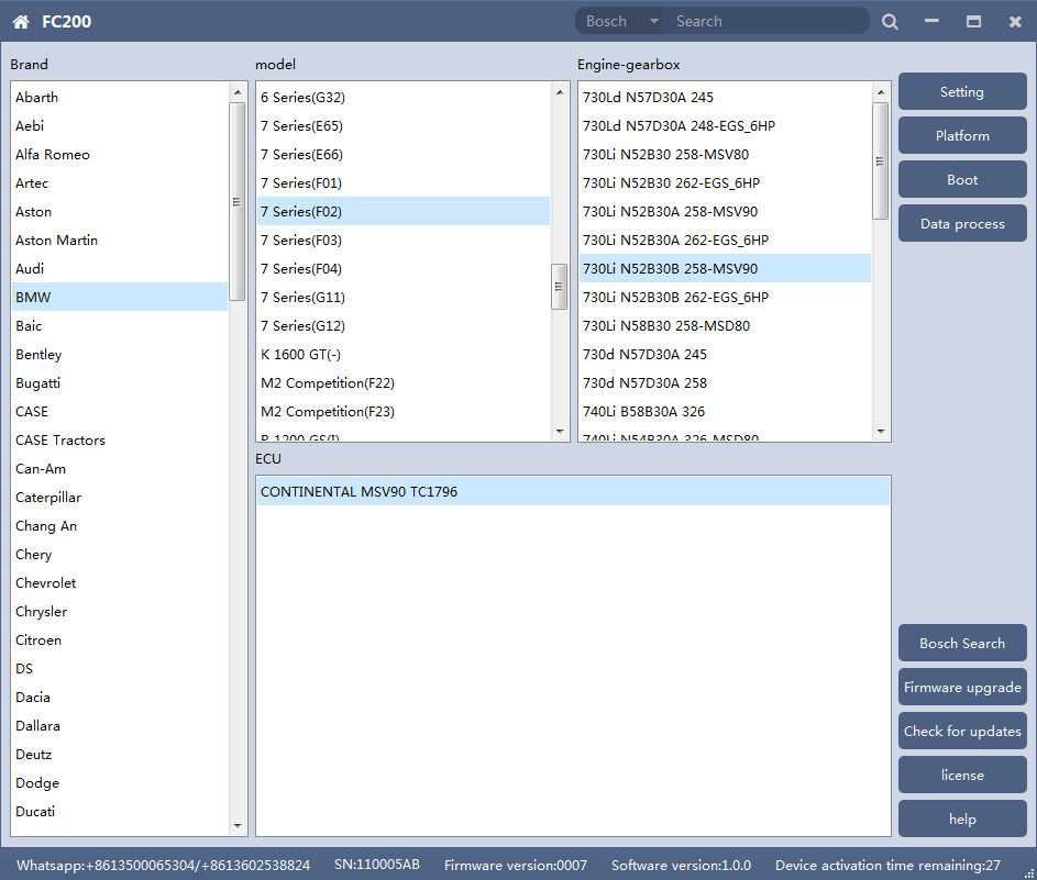
2. MSV90/80/MSD87/85/ 81/80/SIM271 FC200 currently supports the cloning and ISN reading of BMW models MSV90/80/MSD87/85/81/80 (E series, F series) and Mercedes-Benz SIM271 ECU. 1. Determine the type of ECU according to the vehicle model, and select the correct model, otherwise the normal operation will not be possible.The MSV90 is used for description below.
After selecting the correct ECU model, the “Platform” button will appear on the right. As shown in the figure above, click the “Platform” button to enter the ECU operation interface. 2. View wiring diagram
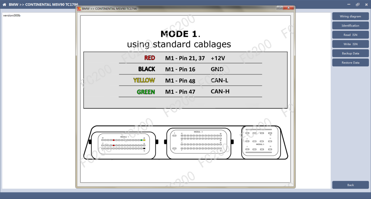
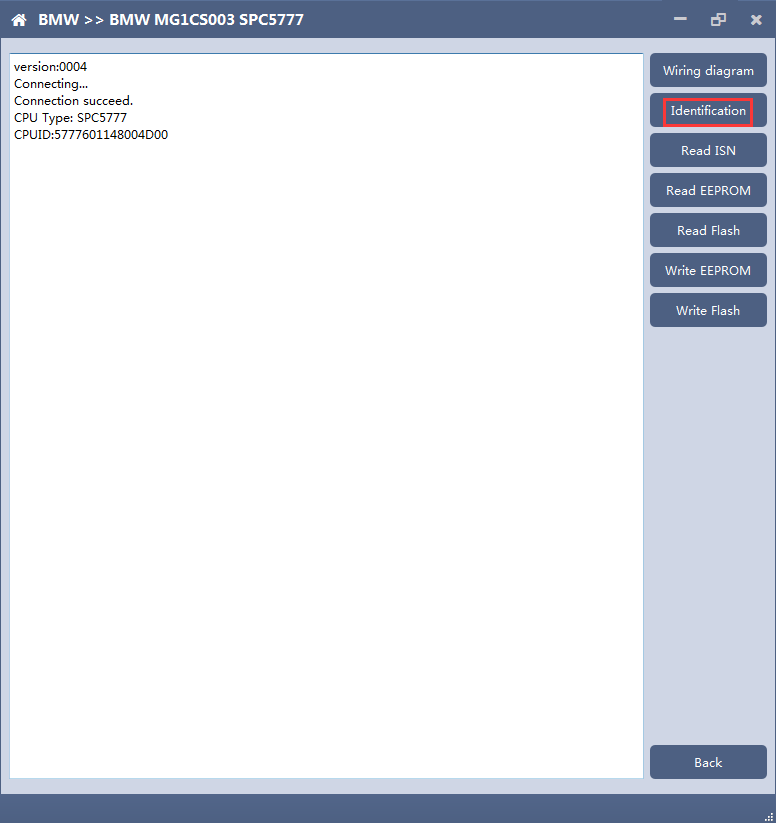
Click the “Wiring Diagram” button to view the ECU wiring diagram, connect the wiring harness correctly according to the wiring diagram, and connect with the device, plug in the device DC12V interface with 12V power supply. 3. Identifying the ECU
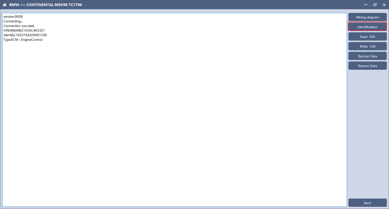
Click the “Identify” button to read the ECU related information, as shown in the figure above. 4. Reading ISN
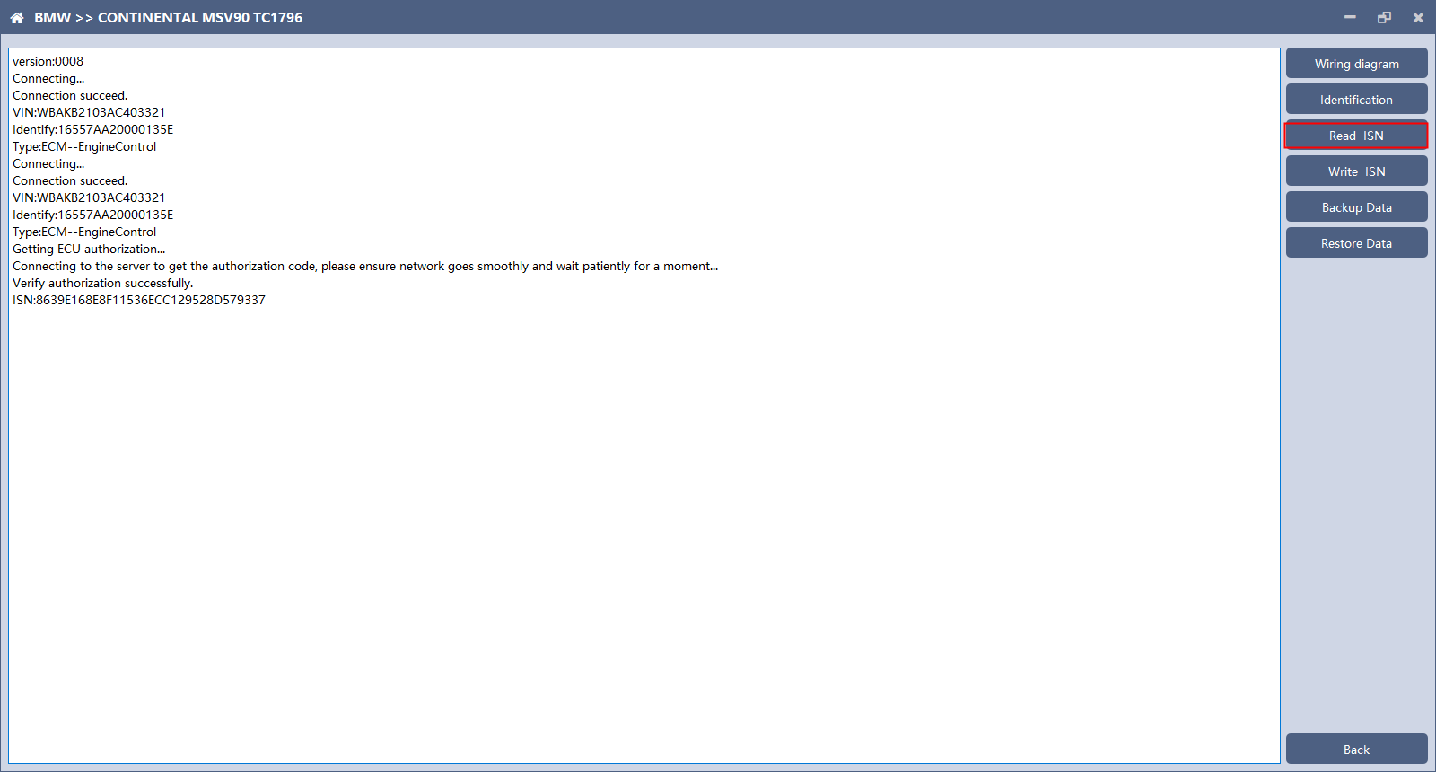
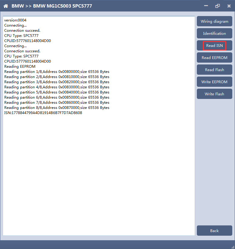
Click the “Read ISN” button to read the ISN. 5. Backup Data
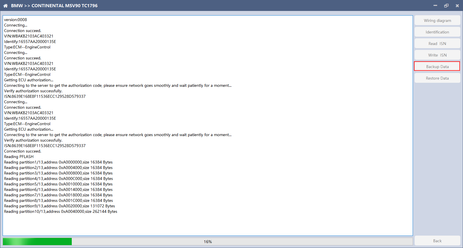
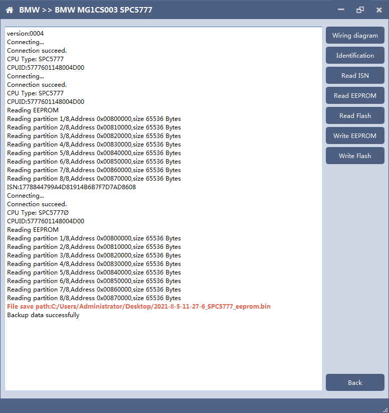
Click “Backup Data” to back up the ECU data. After reading, please save the data for subsequent use. 6. Data Restore
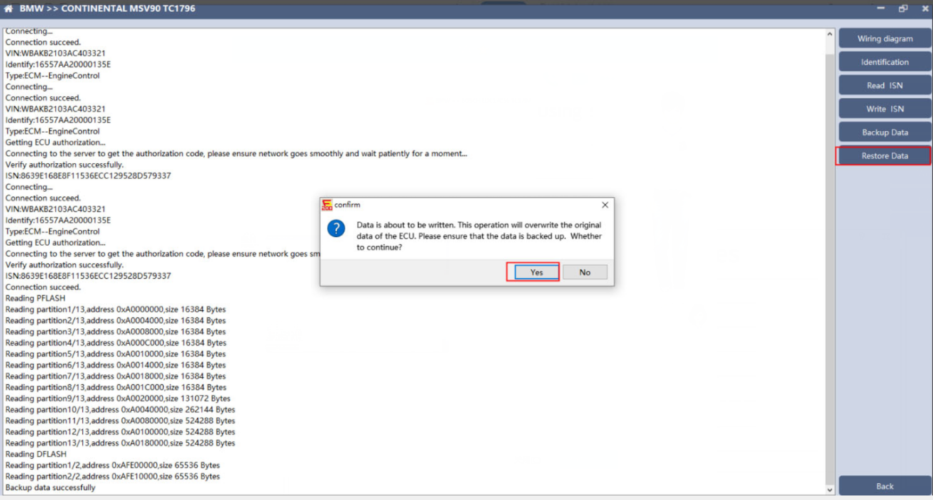
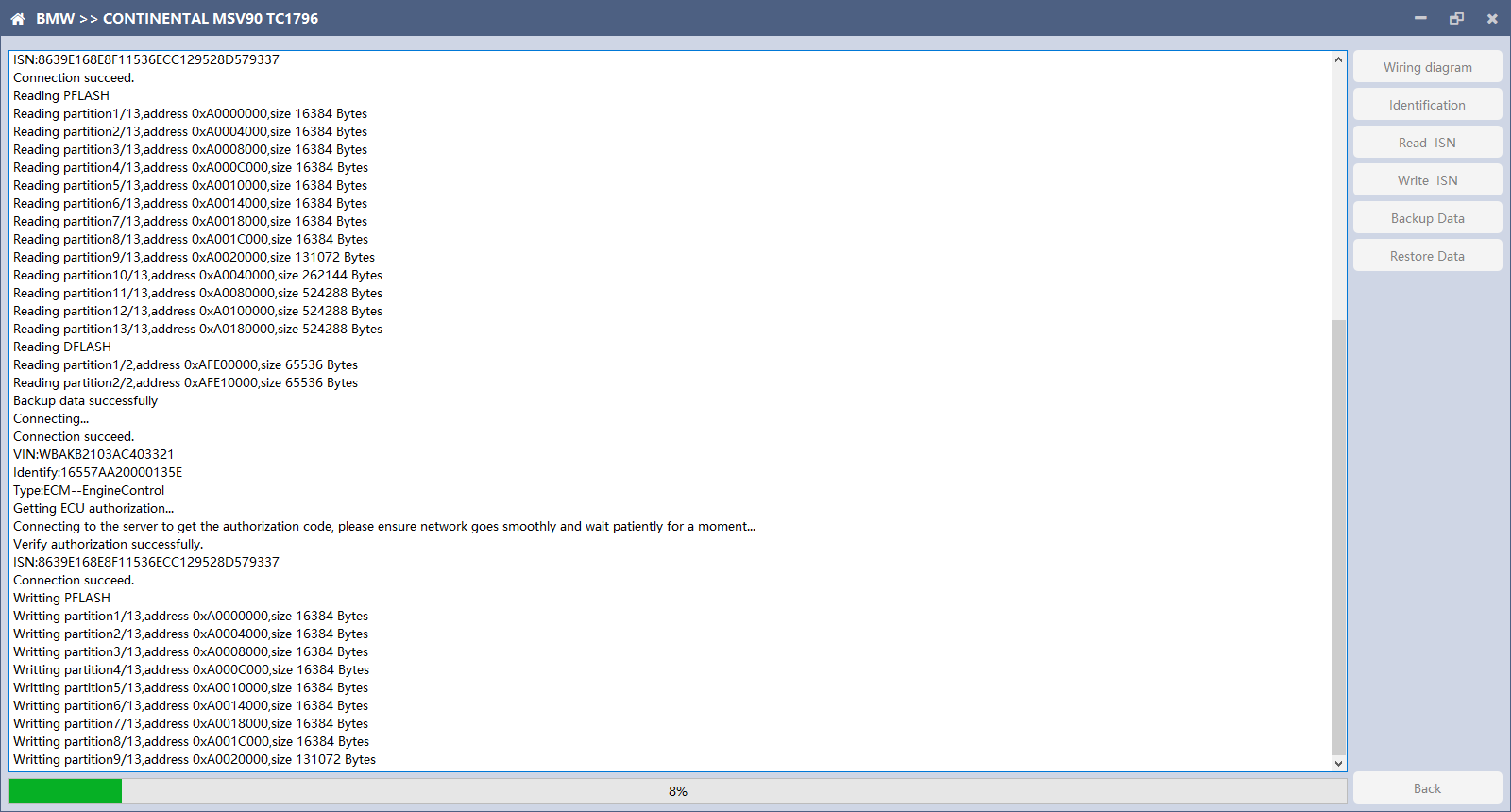
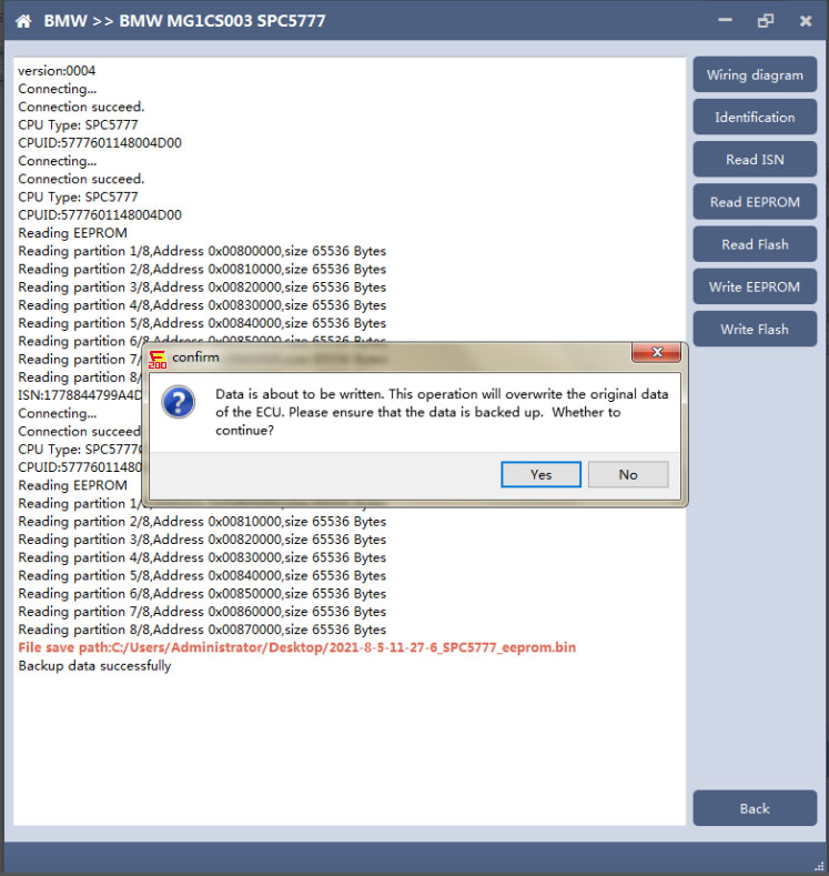
Click “Restore Data” to write the ECU data. Before writing, please make sure the data is backed up. The restored data will overwrite the current ECU data. The data can be the data of the current ECU or other ECU of the same type.
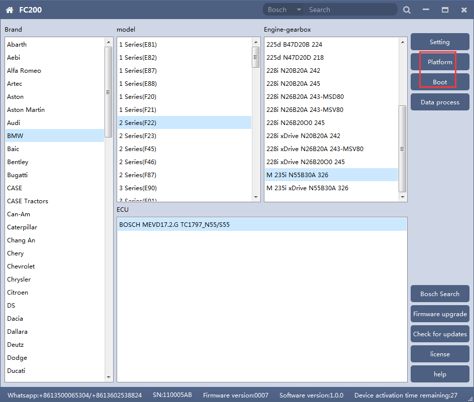
Note: During the process of data recovery, it is strictly forbidden to disconnect the device power or disconnect the device, otherwise it may cause damage to the ECU; if the software is unexpectedly shut down or the computer is shut down or crashed unexpectedly during the process of data recovery, please do not disconnect the device power or device Connect for 15 minutes, and the device can complete data recovery independently. 3. N13/N20/N55/B38/TC17X 1. Determine the type of ECU according to the vehicle model, and select the correct model, otherwise it will not operate normally.The following is described with N55.
After selecting the correct ECU model, the “Platform” button will appear on the right. As shown in the figure above, click the “Platform” button to enter the ECU operation interface. 2. View wiring diagram
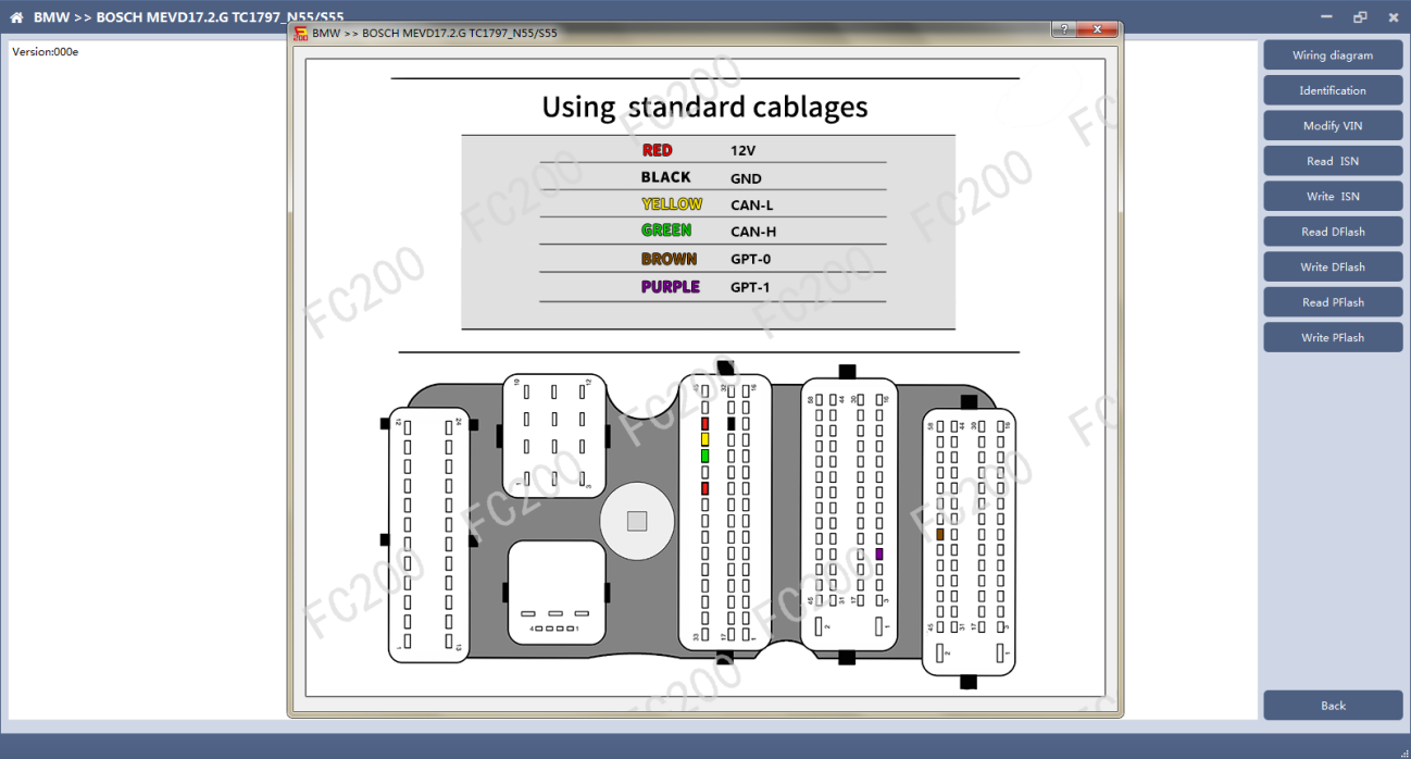
Click the “Wiring Diagram” button to view the ECU wiring diagram, connect the wiring harness correctly according to the wiring diagram, and connect with the device, plug in the device DC12V interface with 12V power supply. 3. Identifying the ECU
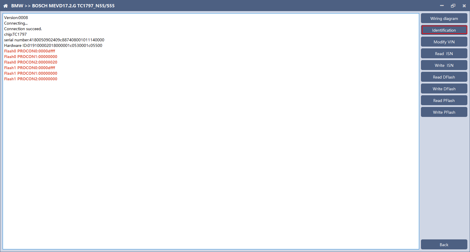
Click the “Identification” button to read the ECU related information, as shown in the figure above. 4. Reading ISN
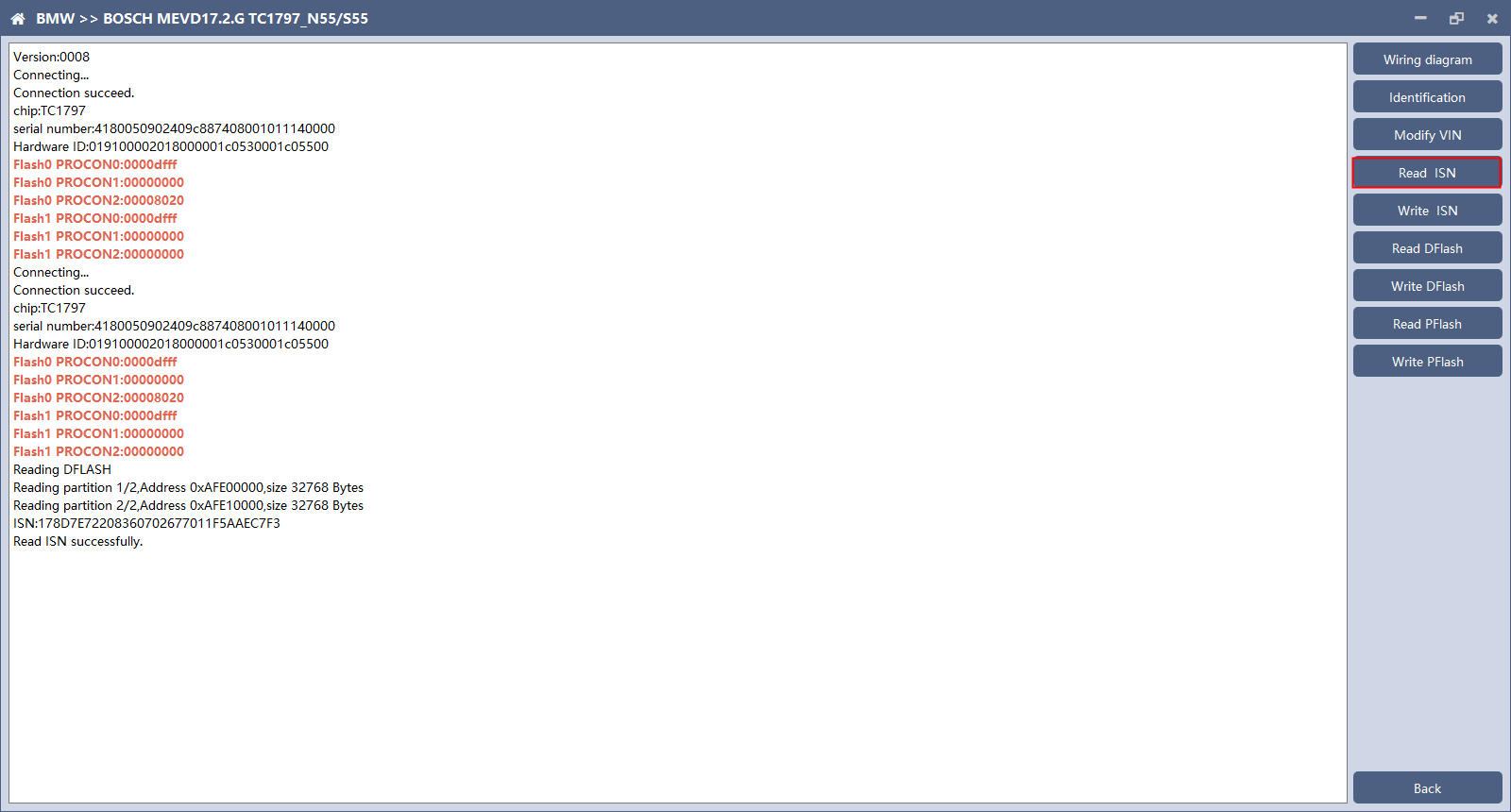
Click the “Read ISN” button to start reading the ISN. Wait for a while to complete the reading of the ISN. 5. Writing ISN
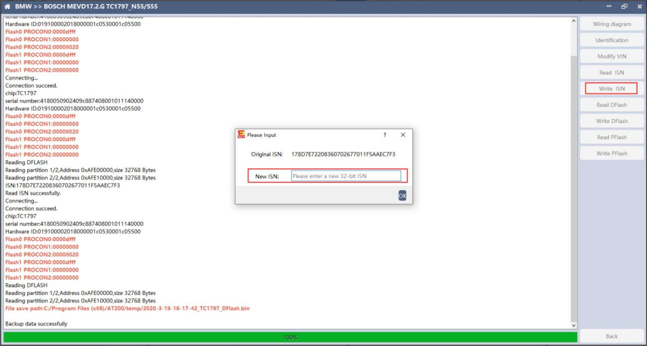
Enter the new ISN in the edit box, and click the “OK” button to start writing the ISN.
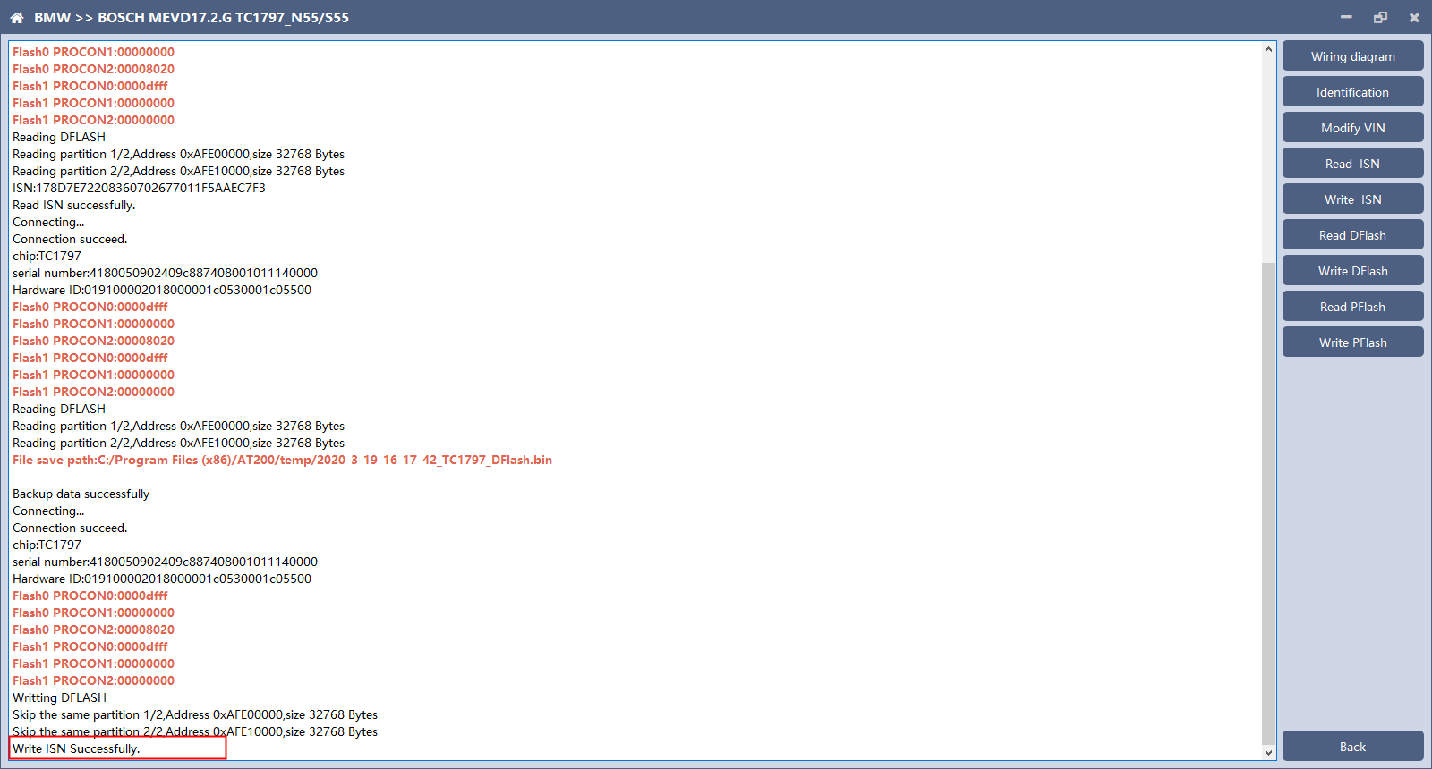
Writing successfully。 6. Modifying VIN
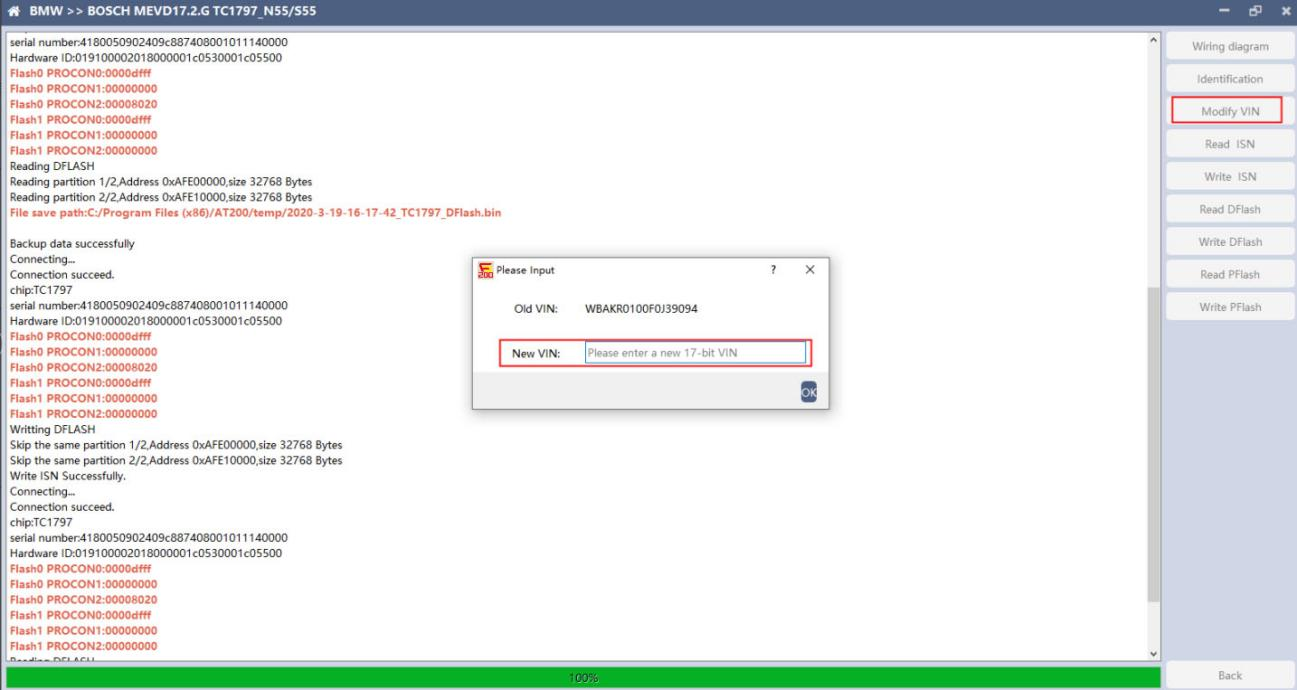
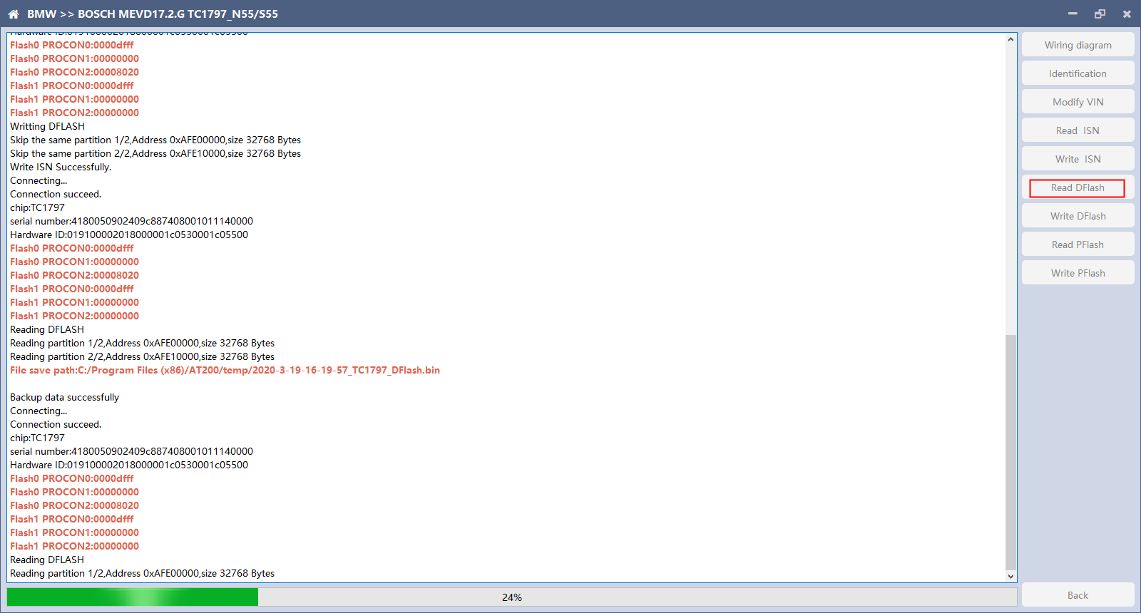
Enter the new VIN in the edit box, click the “OK” button to start writing VIN 7. Reading DFlash. PFlash Take reading DFlash as an example:
Click “Backup Data” to back up the ECU data. After reading, please save the data for subsequent use. 8. Writing DFlash. PFlash
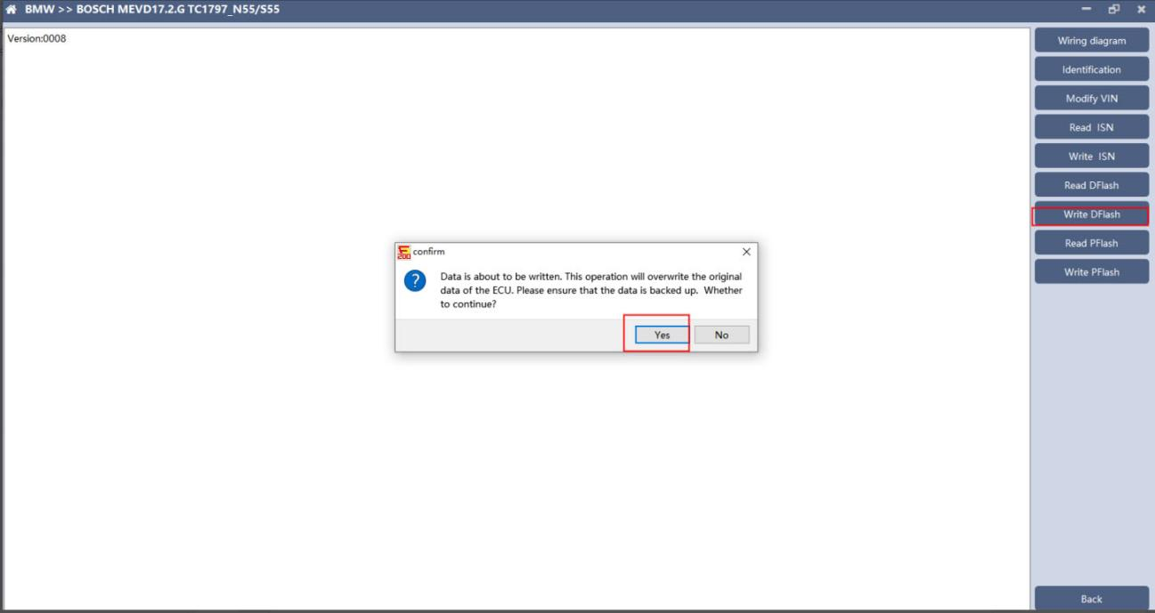
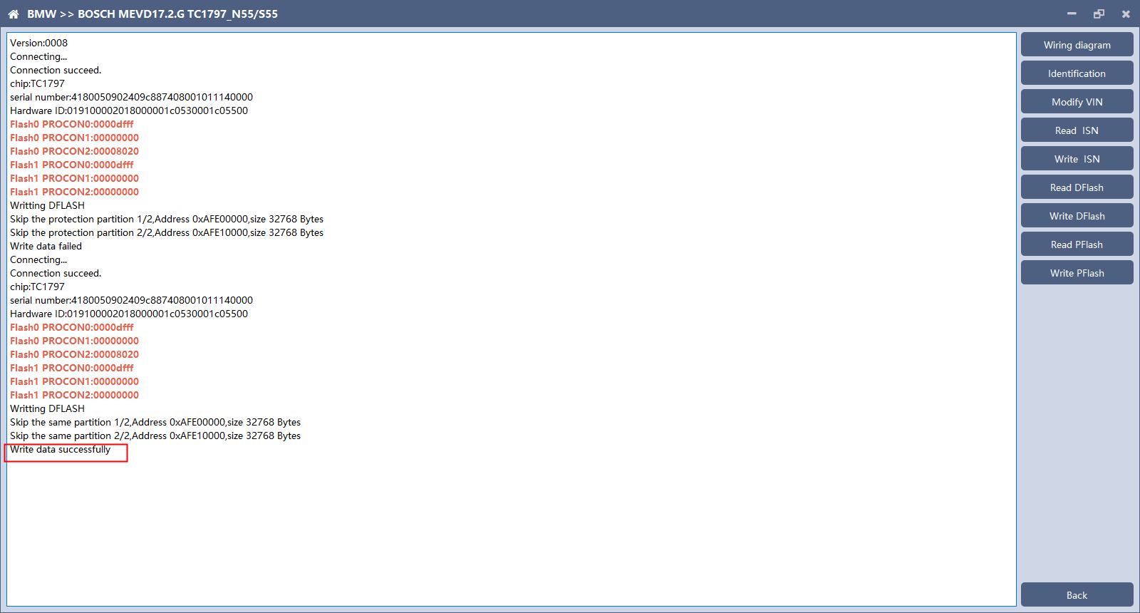
Click “write DFlash” to write the ECU data. Please make sure the data is backed up before writing. The restored data will overwrite the current ECU data. The data can be the data of the current ECU or other ECU of the same type.
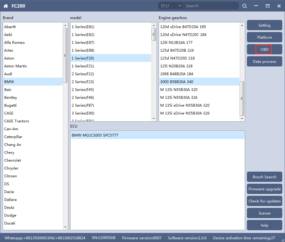
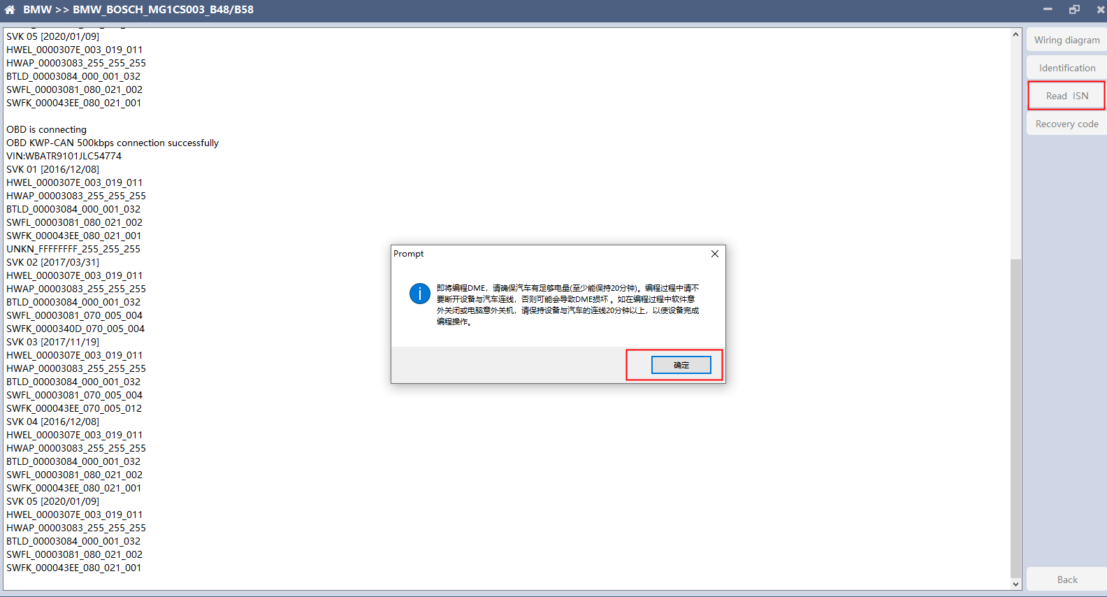
Note: During the data recovery process, it is strictly forbidden to disconnect the power supply or disconnect the device, otherwise it may cause ECU damage; if the software is shut down unexpectedly or the computer is shut down or crashed unexpectedly during the data recovery process, please do not disconnect the power supply or device Connect for 15 minutes, and the device can complete data recovery independently. 4. B48/B58 1 OBD read ISN 1.1 Determine the type of ECU according to the model, and select the correct model, otherwise it will not operate normally.The following is described with B48.
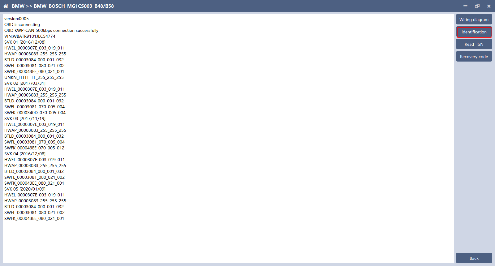
1.2 Identifying ECU
1.3 Reading ISN
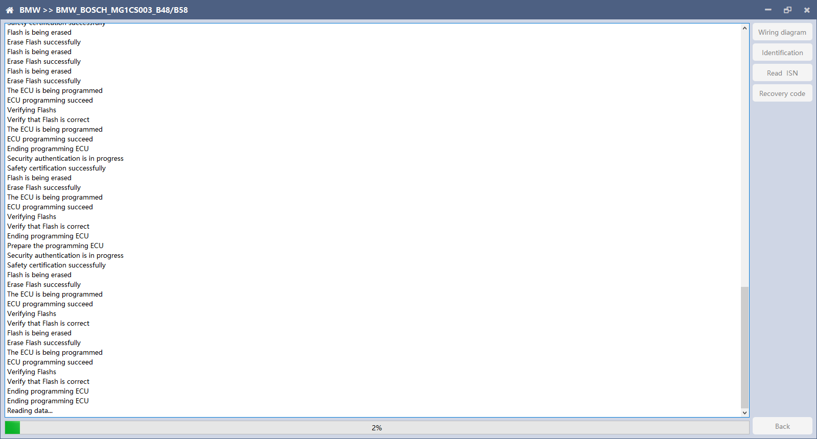
Click the “Read ISN” button to start reading the ISN. If it is the first reading, you need to program the ECU before reading. The programming time will take about 25 minutes, please be patient.
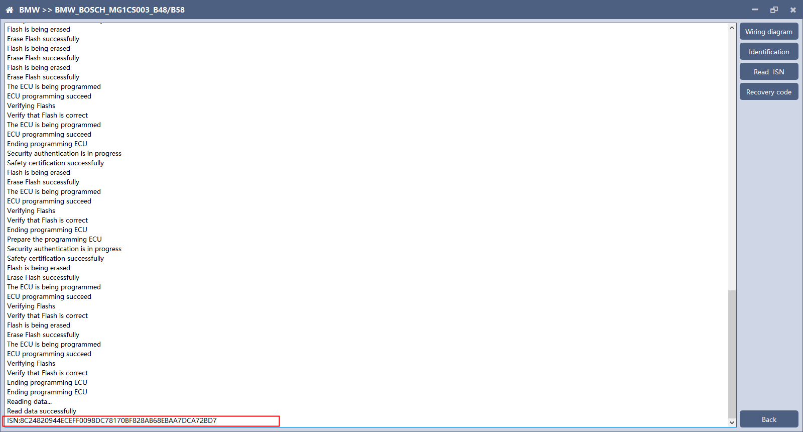
After the programming is completed, if there is a coding file before the ECU programming, the coding recovery will be performed automatically. After programming, the software starts to read data, as shown in the figure above.
Finish reading the ISN. 2. Read ISN on bench
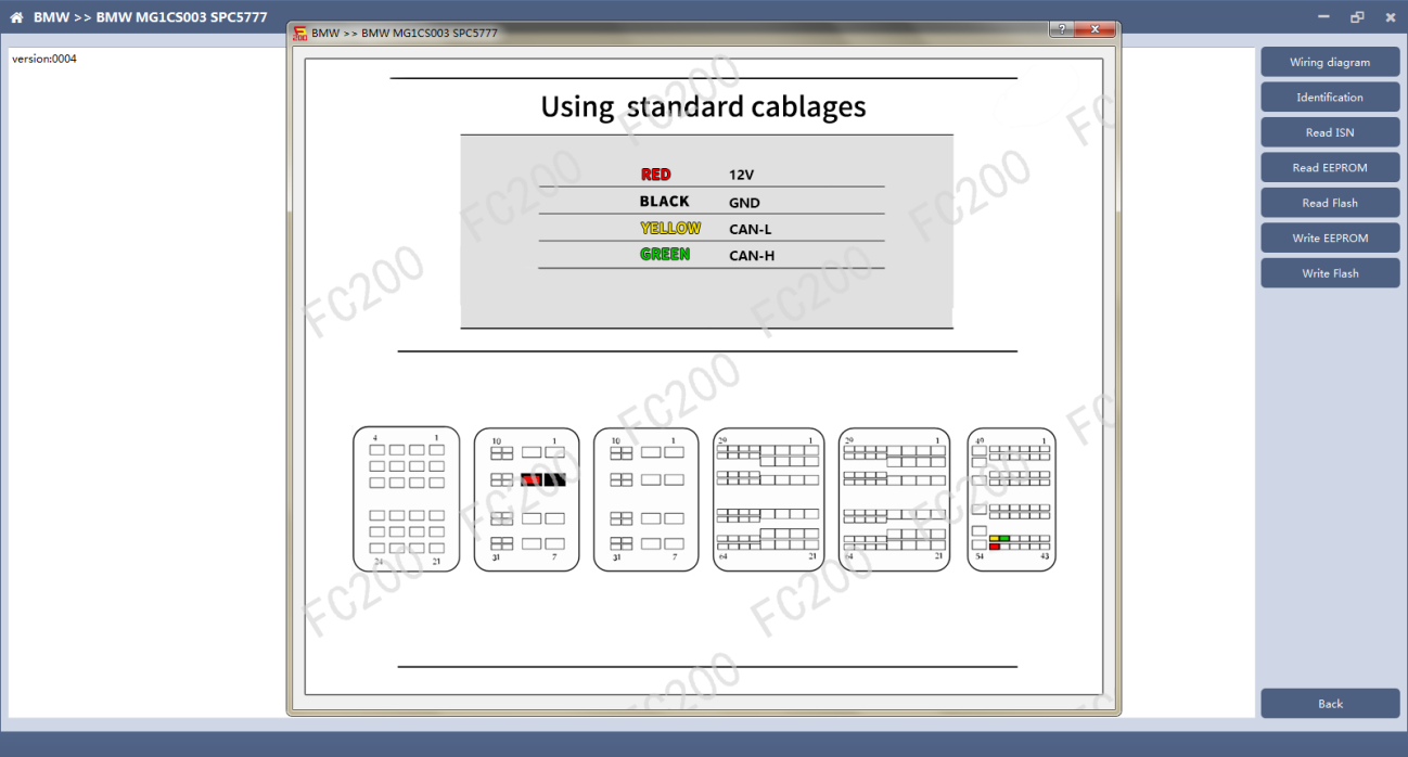
After selecting the correct ECU model, the “Platform” button will appear on the right. As shown in the figure above, click the “Platform” button to enter the ECU operation interface. 2.2 View wiring diagram
Click the “Wiring Diagram” button to view the ECU wiring diagram, connect the wiring harness correctly according to the wiring diagram, and connect with the device, plug in the device DC12V interface with 12V power supply. 2.3 Identifying the ECU How-to-use-CG-FC-200-ECU-Programmer-34 2.4 Reading ISN
2.5 Reading EEPROM/Flash
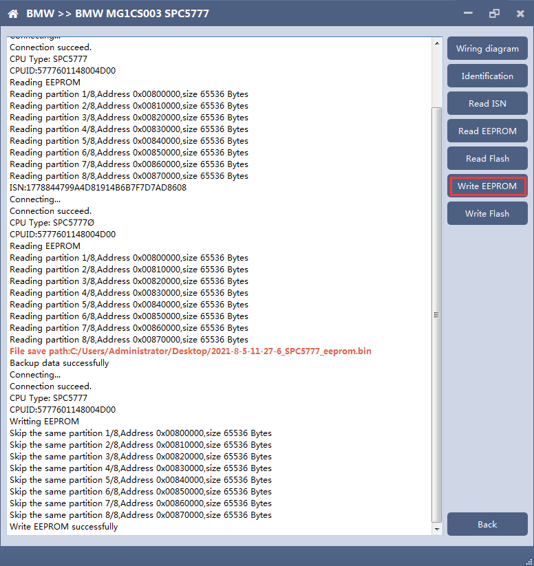
2.6 Writing EEPROM/Flash
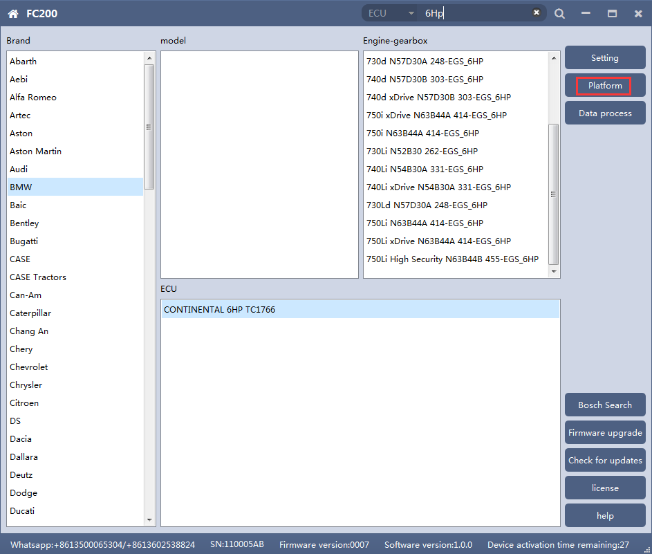
Note: During the data recovery process, it is strictly forbidden to disconnect the power supply or disconnect the device, otherwise it may cause ECU damage; if the software is shut down unexpectedly or the computer is shut down or crashed unexpectedly during the data recovery process, please do not disconnect the power supply or device Connect for 15 minutes, and the device can complete data recovery independently. 5. 6HP 1. Determine the ECU type according to the vehicle model, and select the correct model, otherwise it will not operate normally.
After selecting the correct ECU model, the “Platform” button will appear on the right. As shown in the figure above, click the “Platform” button to enter the ECU operation interface. 2. View wiring diagram
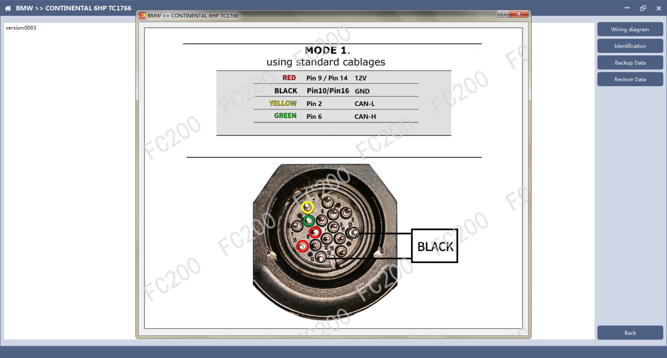
Click the “Wiring Diagram” button to view the ECU wiring diagram, connect the wiring harness correctly according to the wiring diagram, and connect with the device, plug in the device DC12V interface with 12V power supply. 3. Identifying ECU
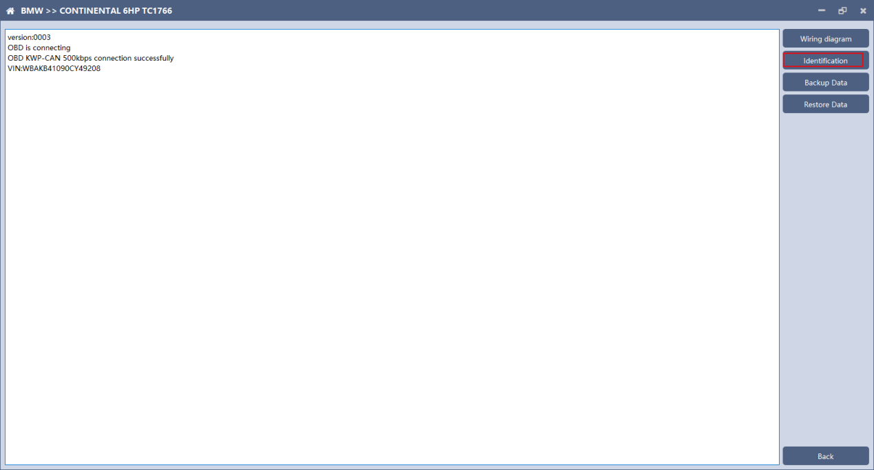
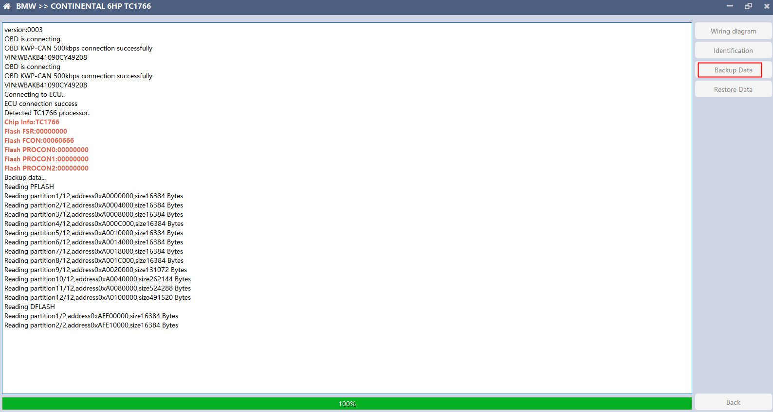
Click the “Identification” button to read the ECU related information, as shown above 4. Backup Data
Click “Backup Data” to back up the ECU data. After reading, please save the data for subsequent use. 5. Data Restore
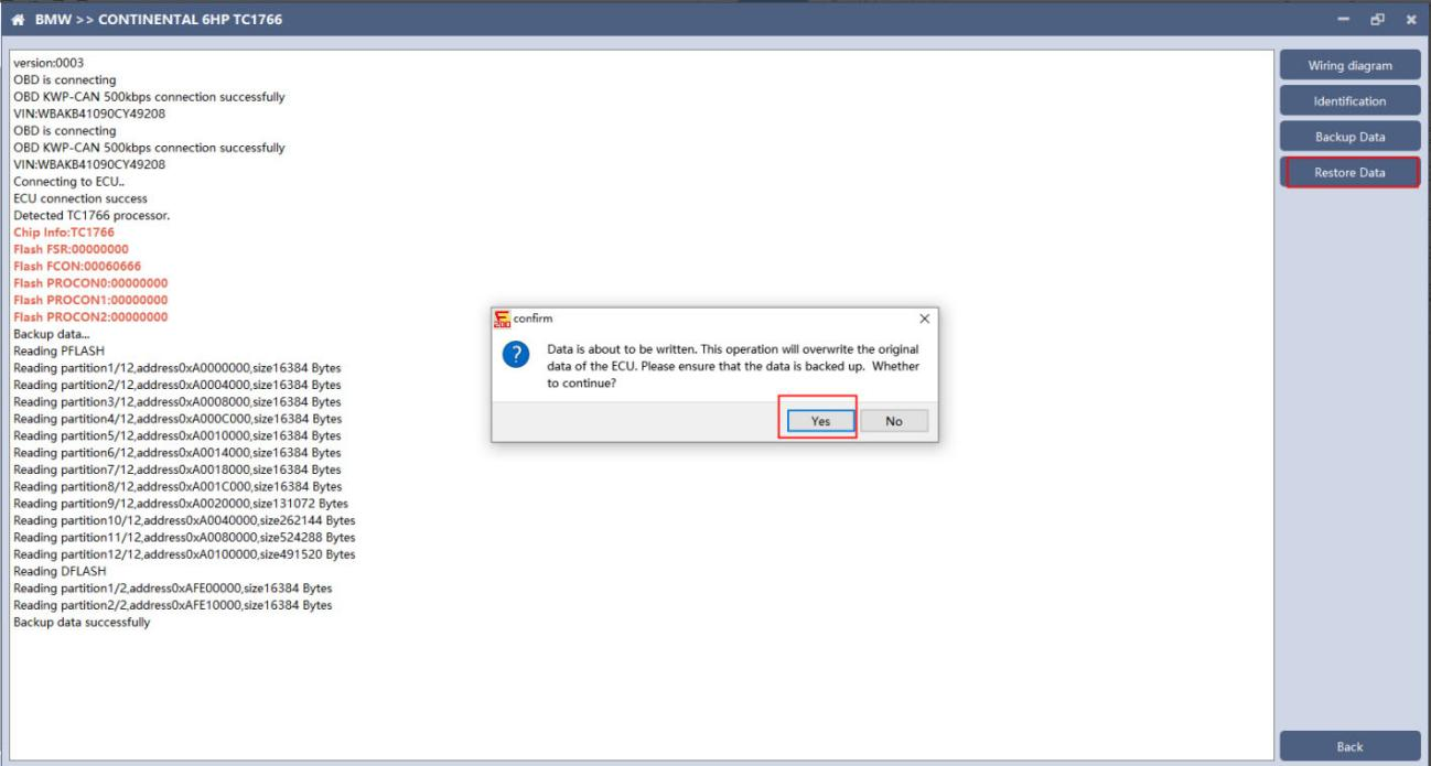
Click “Restore Data” to write the ECU data. Please make sure the data is backed up before writing. The restored data will overwrite the current ECU data. The data can be the data of the current ECU or other ECUs of the same type.
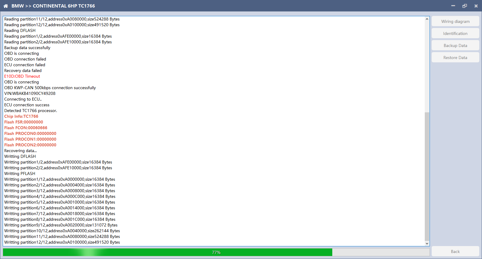
Note: During the data restore process, it is strictly forbidden to disconnect the device from the power or disconnect the device; if the software is unexpectedly shut down or the computer is shut down or crashed unexpectedly during the data recovery process, please do not disconnect the device power or the device connection for 15 minutes , The device can complete the data restore independently. 6. BOSCH BOOT(Boot)read and write data
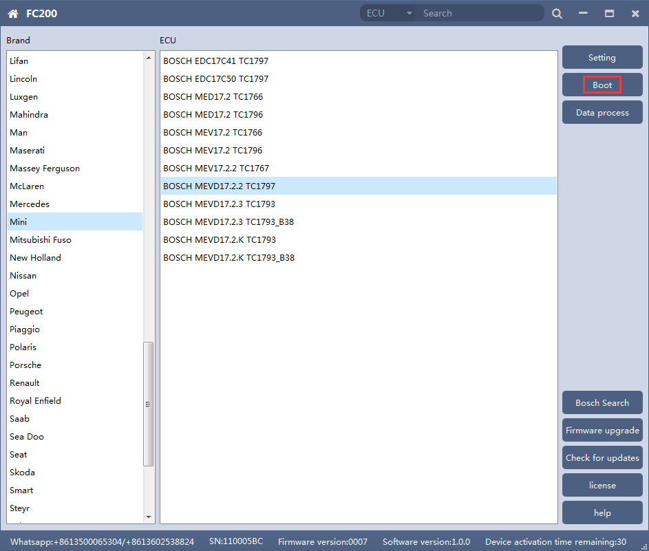
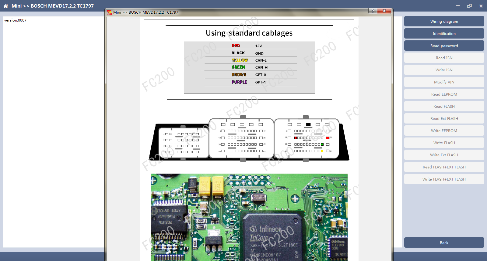
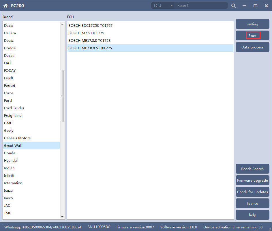
After choosing correct ecu type, there will show a“Boot”button as shown picture above. 2. Check the diagram in software
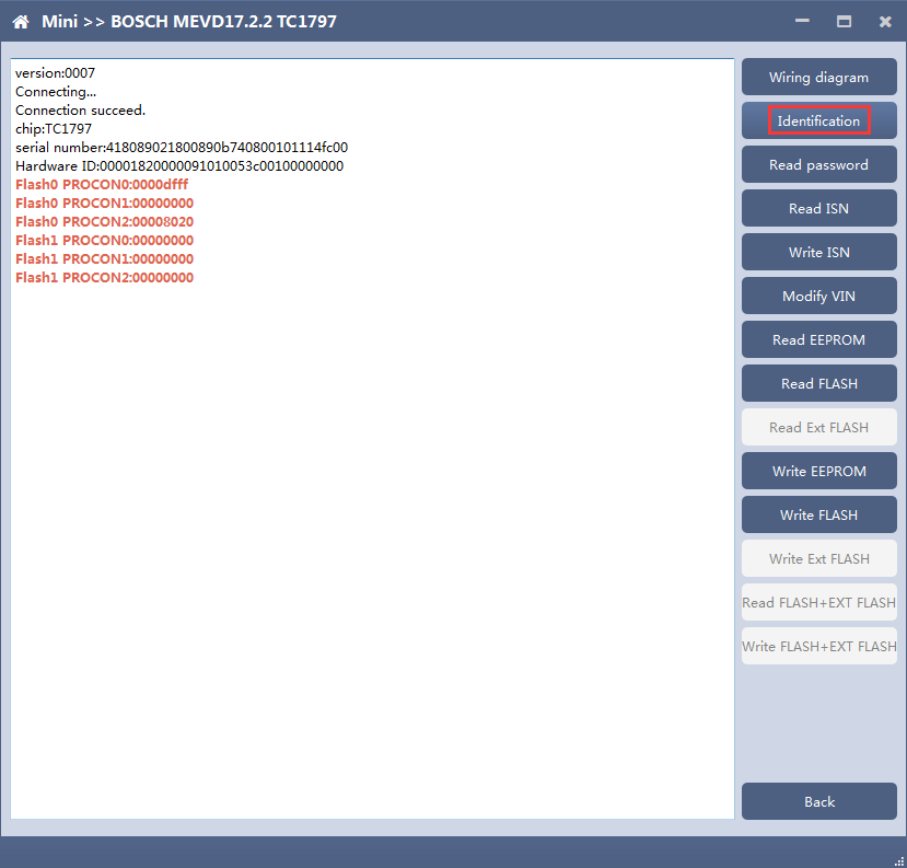
3. Identify ECU
4. Read password
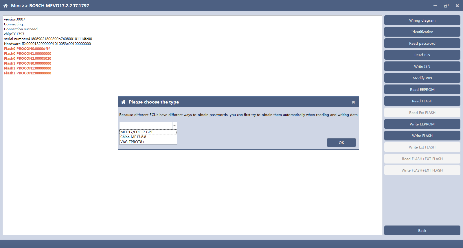
Pop up option box when reading password and select correct type. 5. Read/write Pflash
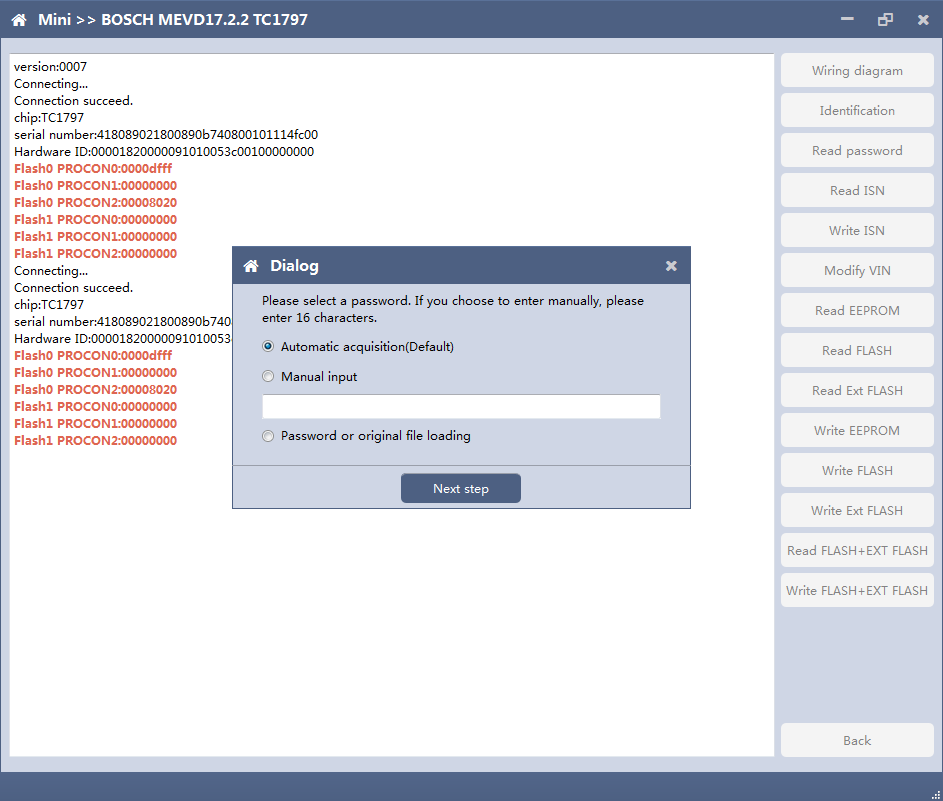
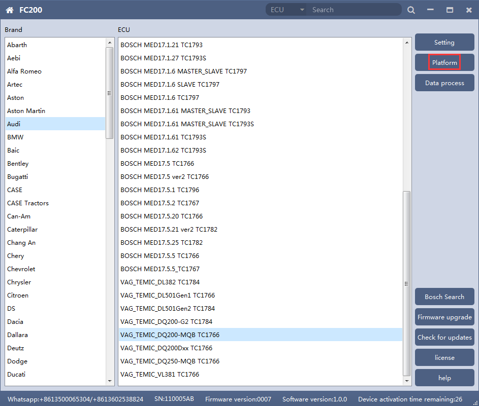
When reading and writing flash, please select automatic acquisition first. If it is not successful, please try other input methods. 7. Volkswagen EGS read and write Flash on bench
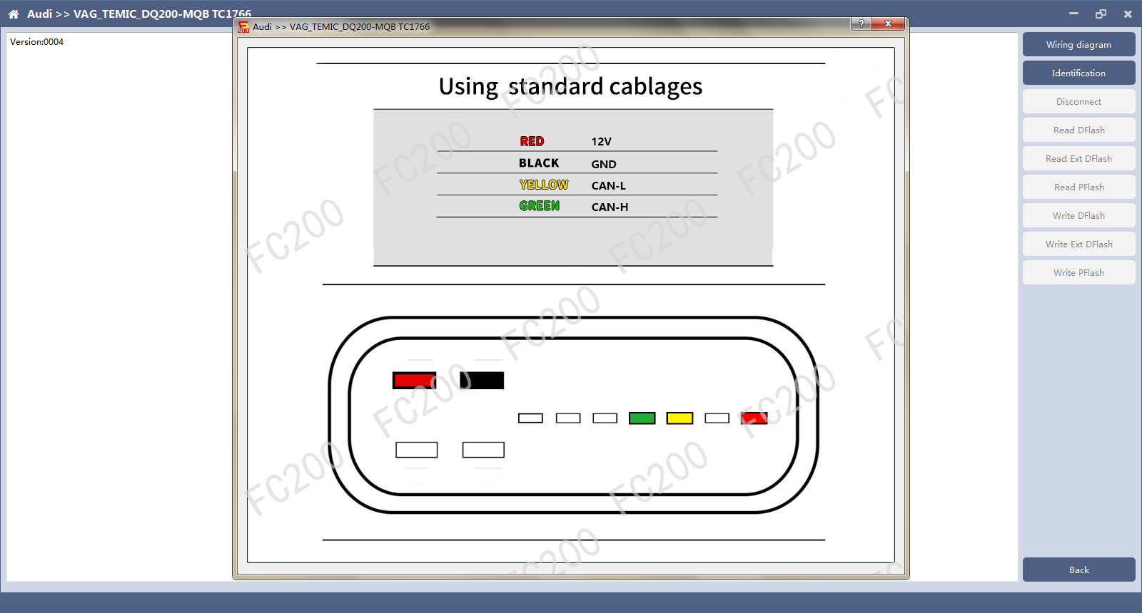
2. Check diagram
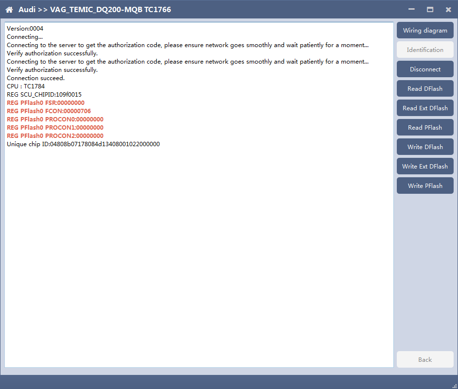
3. Identify ECU
After connecting to DQ200, the “identify” button will be grayed out. You can proceed to the next step. When you click “disconnect”, you can identify again.
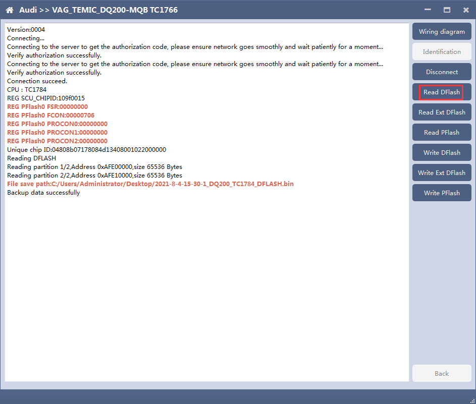
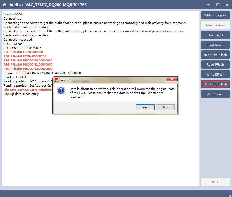
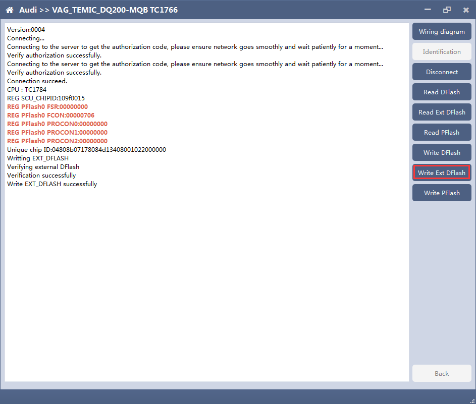
5. Write DFlash. EXT DFlash and PFlash
Back up original data before writing flash. 8. BOSCH ST10 series(Boot) read and write data
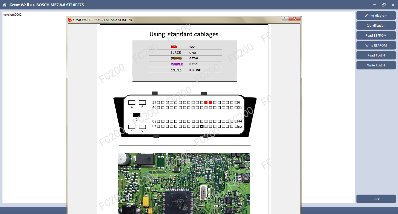
2. Check diagram
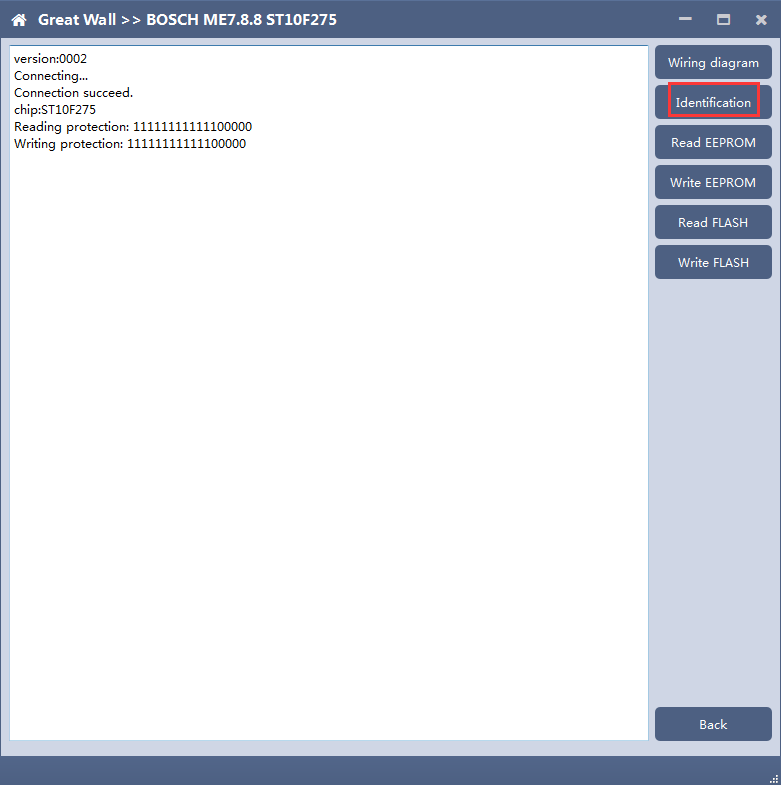
3 Identification
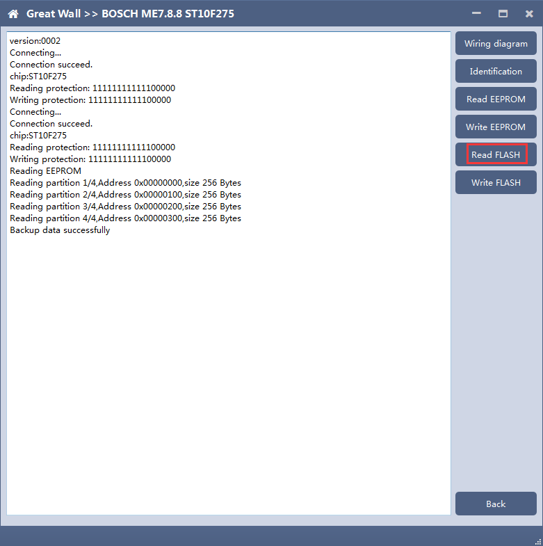
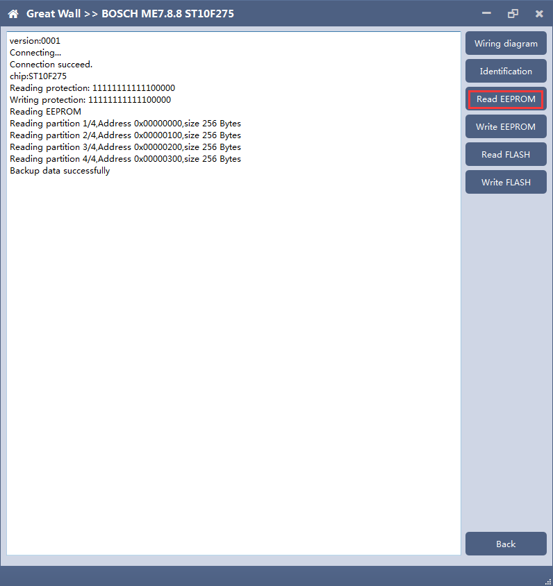
4. Read EEPROM and FLASH
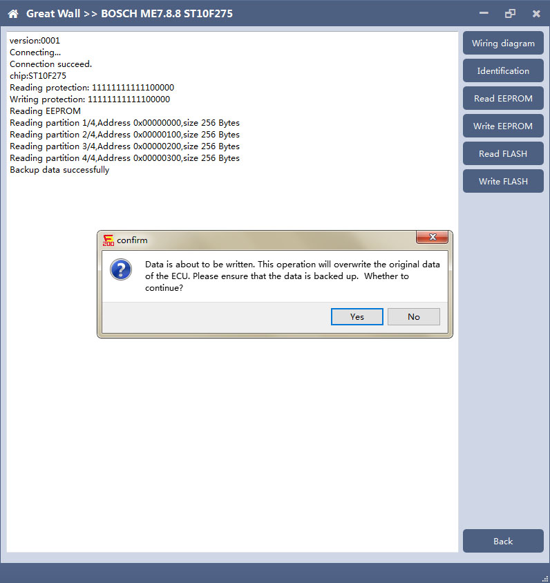
5. Write EEPROM and FLASH
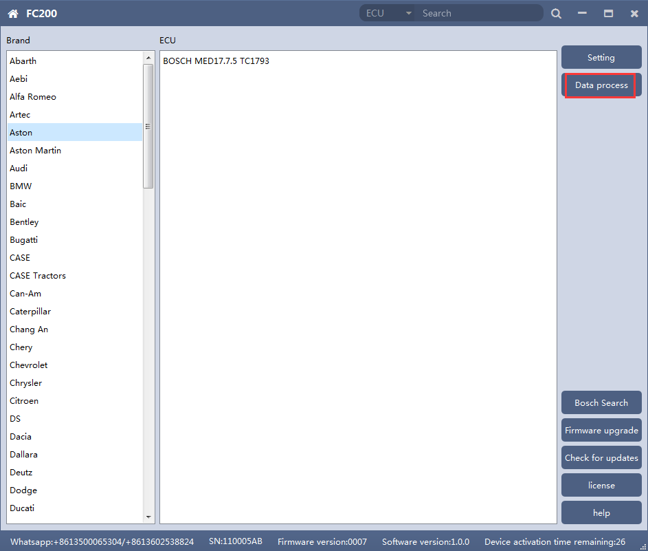
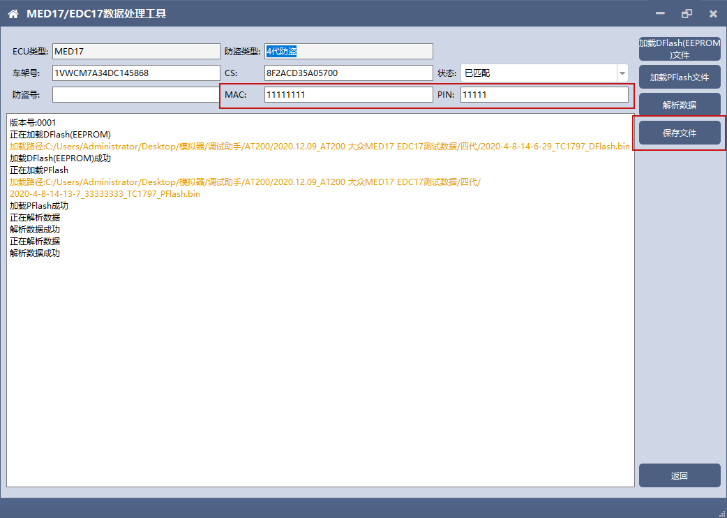
Note: in the process of writing data, it is strictly forbidden to disconnect the power supply or the connection of the device; if the software is shut down or the computer is shut down or crashes unexpectedly in the process of writing data, please do not disconnect the power supply or the connection of the device, and keep it for 15 minutes. The device can recover the data independently. 9. MED17/EDC17 data process tool FC200 currently support(Generation 4 and 5 anti theft of AUDI/SEAT/SKODA/VOLKSWAGEN)ECU data parsing and modification.
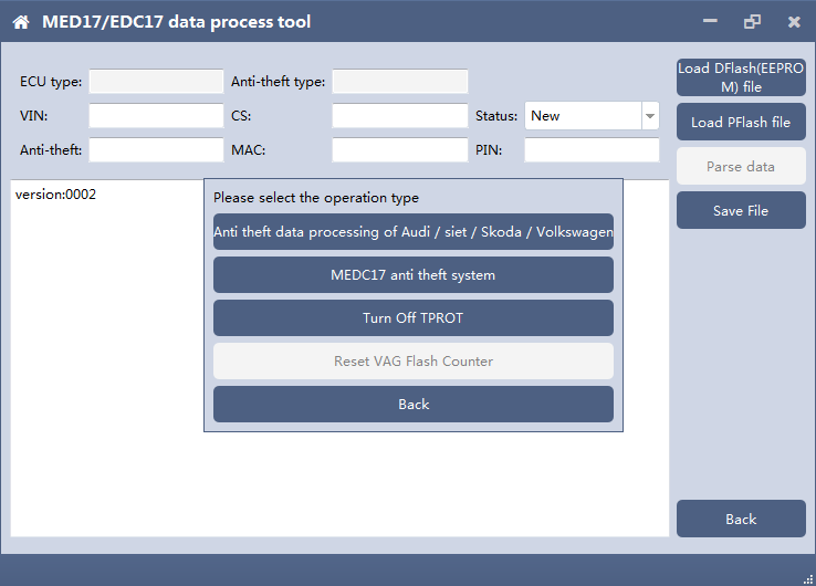
2. Select operation type
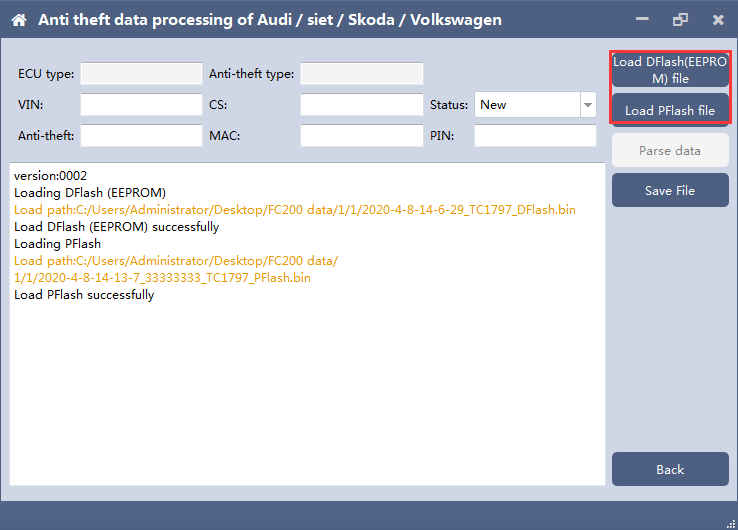
3. AUDI/SEAT/SKODA/VOLKSWAGEN anti-thief data process function
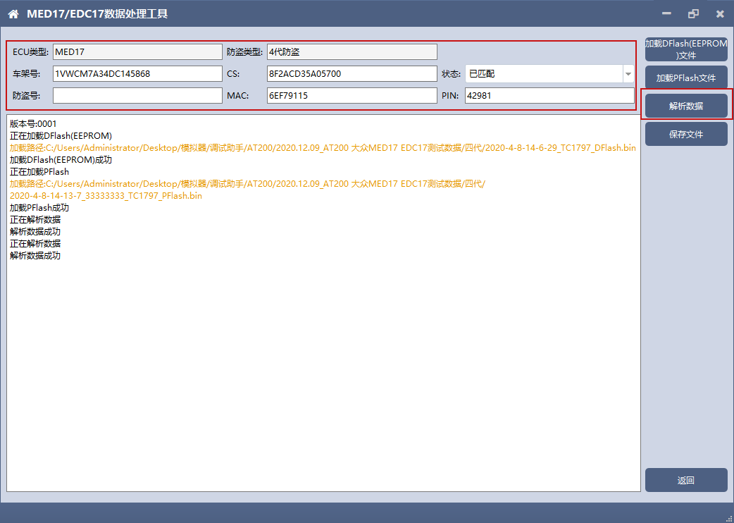
3.2 Parsing data
3.3 Modify the data and save the file
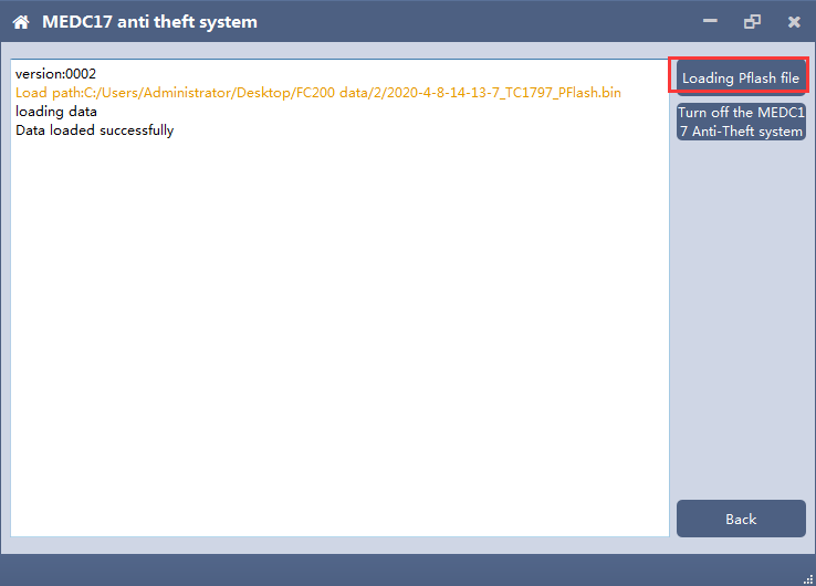
4. MEDC17 anti-theft system function
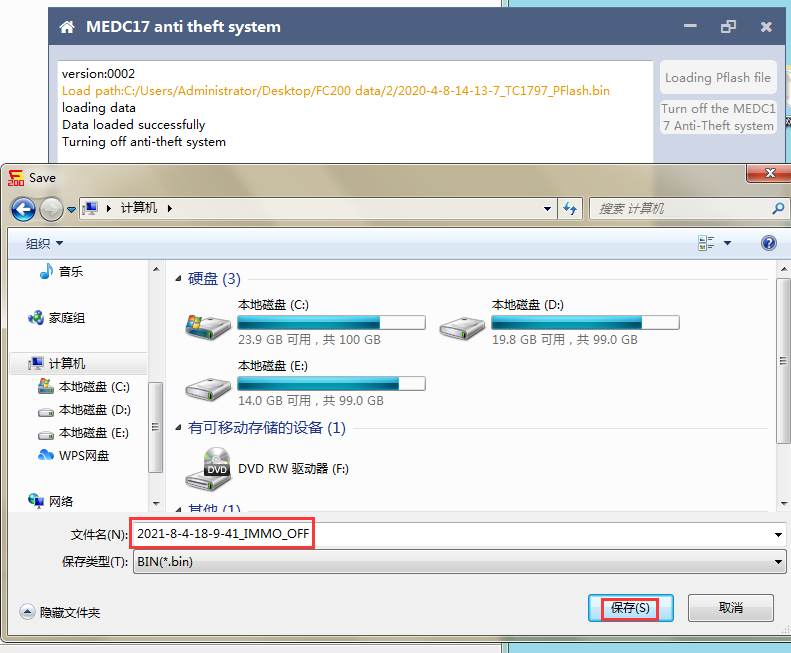
4.2 Turn off the MEDC17 anti-theft system and save file
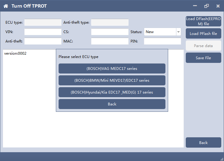
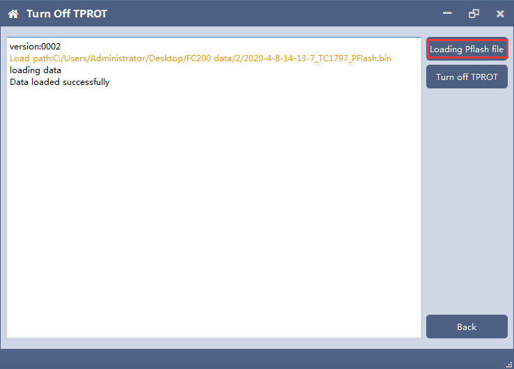
5. Close TPROT
5.2 Load PFLASH data
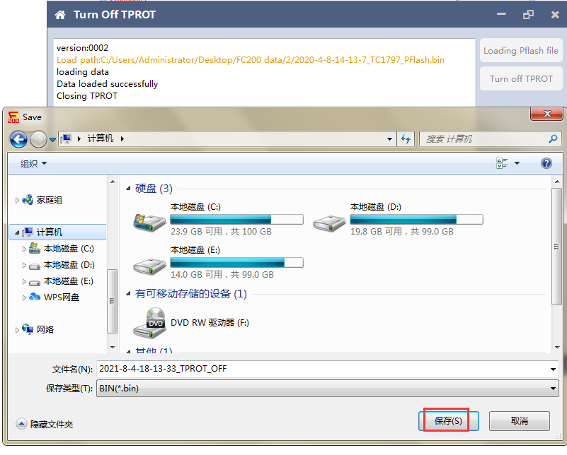
5.3 Close TPROT and save the file.
|
|
| ( 休閒生活|其他 ) |